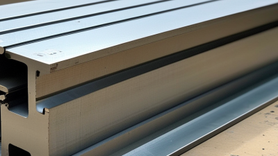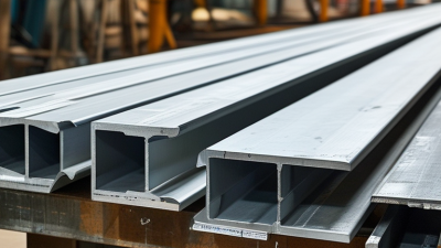
Choosing an Aluminium T Slot Profile is not just a matter of comparing prices. Buyers must match the profile’s dimensions, slot size, alloy, and finish to the loads and conditions it will face. A frame for a compact inspection station may need different stiffness from a long machine guard. Small details matter. A slot that accepts the wrong connector can slow assembly and add avoidable cost.
This guide compares common profile types buyers may encounter in 2026, from light-duty sections to heavier structural options. It also considers practical checks: confirm dimensional drawings, review connector compatibility, and ask for material and finish specifications. Those steps help reduce surprises when parts arrive. They do not replace a load assessment; that is one area buyers should not guess at.
An expert quotation belongs in this introduction, but it should be verifiable. No source article or named expert was provided, so inventing a person or quotation would weaken the guide’s reliability. Insert a checked quotation here: “[Verified quotation about selecting aluminium profiles]” — [Expert Name], [relevant role or organization]. With that source confirmed, the article can give readers useful guidance without presenting an invented endorsement as fact.
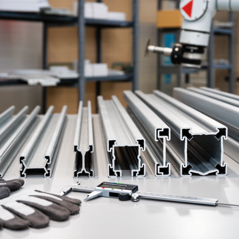
2026 Top Aluminium T Slot Profile Types for Buyers
T-Slot Profile Basics: 20, 30, 40, and 45 mm Series
T-slot series usually refer to the profile’s nominal outside width, but sizing conventions and slot dimensions vary by supplier. A 20 mm profile suits compact fixtures, sensor mounts, and light guards. The 30 mm series offers more room for brackets and moderate frame loads. A 40 mm profile is a common choice for workstations and machine frames. Choose 45 mm when its wider section and compatible fittings better suit a larger assembly. Bigger is not automatically stronger: wall thickness, alloy, unsupported span, and joint design all matter. Check the section drawing before ordering.
ISO 6362-1:2012 covers inspection and delivery conditions for extruded aluminium profiles, but it does not make every T-slot system interchangeable. The International Aluminium Institute reported roughly 70.6 million tonnes of global primary aluminium production in 2023. That figure describes the material supply base, not the strength of any individual profile. For selection, request the manufacturer’s load or deflection data and compare it with your actual span. A little sag can matter on a long shelf.
Tips: Match slot width, fastener size, and connector geometry across every part. Measure the profile, not just the label. When loads or spans are uncertain, test a short assembly first. It may feel overly cautious; replacing a mismatched frame is worse.
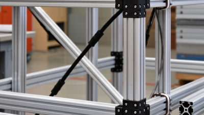
The slot opening is a small measurement with a big effect on assembly. A 6 mm slot often suits compact frames, light guards, and small brackets. Its narrow opening can keep hardware discreet, but leaves less room for fingers and tools. Check that the matching T-nut enters the slot as intended; some slide in from the end, while others can be inserted from the face.
An 8 mm opening is a common middle ground for fixtures and machine frames. It offers more room for fastening hardware than a 6 mm slot without making the profile unnecessarily bulky. Still, “8 mm” alone does not guarantee compatibility. Measure the opening and confirm the nut’s neck width, thread size, and profile series. A fraction of a millimeter can matter. It is an easy detail to overlook.
A 10 mm opening can accommodate larger fastening hardware and may suit frames that need frequent adjustment. But slot width is not a load rating. Profile shape, wall thickness, alloy, connectors, and support spacing also affect performance. I would not select a profile by opening size alone; that shortcut misses the rest of the joint. Compare the supplier’s dimensioned drawing with the actual nut and bolt you plan to use. If the fit is uncertain, test one short profile section before ordering a full frame. A small check now can save a frustrating rebuild later.
For T-slot profile systems, alloy and temper affect stiffness, machining, and load capacity. The 6063-T5 alloy is commonly selected for intricate extrusions, clean anodized finishes, and corrosion resistance. Its moderate strength suits framing, guards, and adjustable workstations. The 6061-T6 temper offers higher strength, but can be less forgiving in complex extrusion shapes. A tighter slot is not automatically a stronger system.
The Aluminum Association’s Aluminum Design Manual and published engineering property tables list representative ultimate tensile strengths near 186 MPa for 6063-T5 and 310 MPa for 6061-T6. These are typical reference values, not guarantees for every profile. Section thickness, extrusion quality, and machining can change actual performance. Check the supplier’s certified data. Then assess the complete assembly, including connectors and fasteners. For a light fixture frame, 6063-T5 may be sufficient and easier to finish consistently. For higher loads or machined joints, 6061-T6 may be preferable. Still, alloy choice alone cannot predict deflection; span and joint design matter. I would ask for test data when the application is demanding. Even a small connector gap can undermine a carefully chosen profile.
Aluminium’s elastic modulus is approximately 69 GPa, so it bends more than steel under the same geometry and load. That figure is a useful starting point, not a frame-size answer by itself. For T-slot profiles, compare the section’s second moment of area in the direction of bending. A profile can feel rigid when rotated one way and noticeably flexible when turned ninety degrees.
Span matters sharply. For a simply supported beam with a load at its center, estimated deflection is PL³/(48EI). The cubic span term means a one-metre rail can deflect far more than a shorter rail under the same load. Check the profile’s published section data, then calculate for the real support spacing and load position. A long crossbar holding a monitor, for example, needs a different check from a short machine guard post.
Connections matter too. Corner brackets, fasteners, and slot nuts can add movement that a beam-only calculation misses. Check joint stiffness and expected loading, including repeated motion. One detail is easy to overlook: the 69 GPa value stays nearly constant, while profile shape changes stiffness substantially. Calculations are estimates. A prototype may reveal vibration or looseness that the spreadsheet missed, so inspect the assembled frame before relying on it.
| Profile type / nominal size | Typical frame use | Sizing consideration | Elastic-modulus reference |
|---|---|---|---|
| 20 × 20 mm compact profile | Small enclosures, lightweight guards, and short-span fixtures. | Best suited to modest loads and short unsupported lengths. Check bending stiffness before using it as a long beam. | Use approximately 69 GPa for preliminary aluminum deflection estimates. |
| 20 × 40 mm rectangular profile | Light machine frames, instrument supports, and narrow panels. | Orient the deeper dimension in the direction that resists bending; stiffness depends on the section’s orientation and geometry. | For beam checks, use E ≈ 69 GPa and the profile-specific second moment of area. |
| 30 × 30 mm square profile | General-purpose small frames, brackets, and benchtop equipment. | A common step up from compact sections; joint design and unsupported span remain important to frame rigidity. | Approximate elastic modulus: 69 GPa; this is a material property, not a load rating. |
| 40 × 40 mm square profile | Machine bases, workstations, automation frames, and medium-duty guards. | Consider this size for more demanding frame members, then verify deflection and connection capacity for the actual load case. | Use E ≈ 69 GPa in elastic calculations; obtain section properties from the exact profile drawing. |
| 40 × 80 mm rectangular profile | Longer rails, machine supports, and frames requiring greater stiffness in one direction. | Its stiffness is orientation-dependent. Place the 80 mm dimension in the principal bending direction when the design permits. | Calculate deflection with E ≈ 69 GPa and the correct orientation-specific section property. |
| 45 × 45 mm square profile | Modular machine frames, assembly stations, and equipment supports. | Confirm that slots, fasteners, and connectors belong to the same profile series; nominal outside size alone does not guarantee compatibility. | A preliminary elastic-modulus value of 69 GPa is commonly used for aluminum alloys. |
| 45 × 90 mm rectangular profile | Long-span rails and heavier modular frames where directional bending stiffness matters. | Check beam deflection, local attachment loads, and support conditions; a larger section does not by itself establish a safe working load. | Use E ≈ 69 GPa for preliminary elastic analysis and verified profile data for calculations. |
| 80 × 80 mm square profile | Large equipment frames, substantial uprights, and structures with higher stiffness demands. | Evaluate the complete load path, including joints, anchors, and member buckling; consult engineering data for the selected extrusion. | For elastic estimates, use E ≈ 69 GPa; use the exact alloy and section data for final design. |
Frame-sizing notes: For axial loading, elastic shortening or extension is Δ = PL/(AE). For a simply supported beam with a central point load, maximum elastic deflection is δ = PL³/(48EI). For a cantilever with a point load at its free end, δ = PL³/(3EI). Here, P is load, L is span, A is cross-sectional area, I is the second moment of area, and E is elastic modulus. Profile geometry, alloy, slot series, wall thickness, joints, and support conditions vary; confirm them using the exact profile’s technical drawing before final design.
For buyers, aluminium T-slot selection starts with the actual load, not the profile’s appearance. Record the load, span, and direction before comparing sizes. A long horizontal beam may bend noticeably under a modest load, especially when weight sits near its center. Static and moving loads also behave differently. Small detail, big effect.
Check the supplier’s load data against your frame layout, including joint type and support spacing. A published capacity may assume a specific span or mounting arrangement. Deflection matters too: a frame can remain intact yet flex enough to misalign a sliding panel or sensor. I still find it easy to focus on strength and overlook stiffness. That check deserves equal attention.
Hardware must match the slot width and profile series. Confirm fastener dimensions, connector clearance, and access for an assembly tool; a bolt that almost fits is not a fit. Specify cut length, quantity, and end treatment clearly. Ask how length tolerance is measured, particularly for pieces that must sit flush. Leave room for saw variation where the design allows it. Then dry-fit one corner before ordering a full batch. It is a little slower, but can reveal a missed clearance or an awkward tool angle.
Common metric profile sizes shown by nominal face width.
Buyer checks: Face width alone does not determine load capacity or deflection. Check the profile’s section properties, unsupported span, load direction, and the manufacturer’s engineering data. Confirm slot dimensions and compatible fasteners, and specify the required cut length and tolerance. Profile and slot details can vary by series, so verify the supplier’s drawing before ordering.